Binary Half Adder Circuit
Adder electronics half wikipedia svg wiki Half adder : circuit diagram,truth table, equation & applications Adder half full gate between difference equation sum geeksforgeeks addition obtained binary output ex
[DIAGRAM] 4 Bit Adder Logic Diagram - MYDIAGRAM.ONLINE
Adder half diagram circuit truth table equation 13+ full adder block diagram Adder subtractor logic combinational circuits bit binary full using subtraction tutorial add adders sub electronics
What is a half adder?
Adder half subtractor binary full carry inputsAdder half xor rangkaian logic ripple adders transistor kombinasi Half adder circuit diagram and truth tableBinary half adder circuit.
Half adder circuit diagramAdder nand combinational circuits implementation sum carry combinations Half adder logic circuit diagramIntroduction to half adder.

Binary half adder
Difference between half adder and full adderHalf adder circuit diagram using nand gate Binary half adder circuitAdder half circuit diagram fig svg following.
Adder bit circuit half make full logic gates first questions electronics cout second puzzle connecting solved whichDraw the circuit diagram of half adder [diagram] 4 bit adder logic diagram4 bit binary adder circuit.

Binary adder and subtractor circuits: half and full adder, subtractor
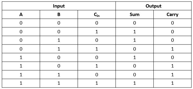
What is adder?Adder truth half table circuit diagram equation using its [diagram] full adder circuit diagram and truth tableHalf adder circuit using basic logic gates.
Full adder logic circuit diagramAdder input outputs along Binary adder/subtractorFull adder circuit diagram.

Logic circuits: half and full adders
Logic gatesAdder (electronics) Adder half binary circuit bit digitalHalf full adders bit two binary addition logic numbers input circuits three figure column.
Half adder : circuit diagram,truth table, equation & applicationsFull adder circuit diagram Half adder truth table and circuit diagramAdder half introduction digital operations.
![[DIAGRAM] 4 Bit Adder Logic Diagram - MYDIAGRAM.ONLINE](https://i2.wp.com/electronicscoach.com/wp-content/uploads/2017/12/logic-diagram-of-2-bit-parallel-binary-adder.jpg)


![[DIAGRAM] Full Adder Circuit Diagram And Truth Table - MYDIAGRAM.ONLINE](https://i2.wp.com/theorycircuit.com/wp-content/uploads/2018/04/half-adder-circuit-diagram-with-truth-table.png)


